What is the Insertion Loss and Return Loss of Components in Optical Fiber Cable?
What is the Insertion Loss and Return Loss of Components in Optical Fiber Cable?
Blog Article
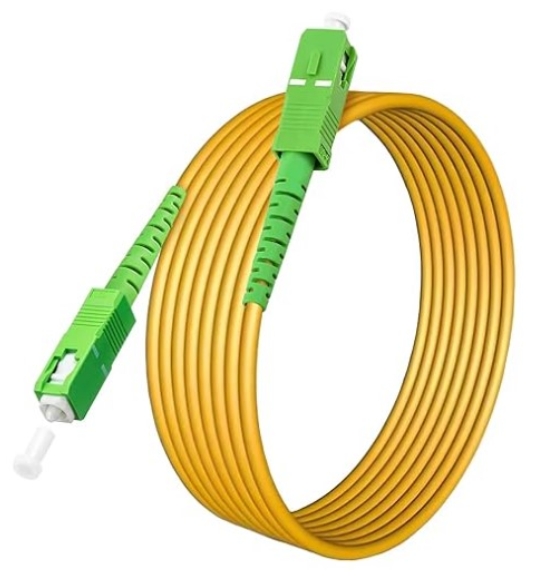
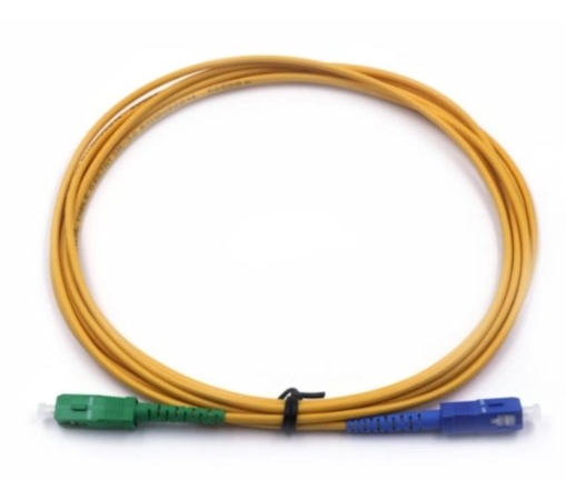
In fiber optic communications, insertion loss and return loss are two important indicators for evaluating the quality of fiber optic cable assemblies. Such as fiber optic connectors, optical jumper fibers, and pigtails. So what is the fiber cable insertion loss? So what is the optical fiber cable return loss?
What is the insertion loss of fiber optic cable assemblies?
Calculation formula: IL = -10 lg (pot/Pin), pot is the output optical power. Pin is the input optical power.
The smaller the value of insertion loss, the better the performance. For example, an insertion loss of 0.3dB is better than 0.5dB. Generally, the attenuation difference between fusion splicing and manual connection (less than 0.1 dB) is smaller than that between fiber optic connectors. Recommended maximum dB loss of data center optical cable assemblies. 15dB for multimode LC fiber patch cords. 15dB for single-mode LC fiber optic patch cords. 20dB for multimode MTP/MPO fiber patch cords. And ≥ 30dB for single-mode MTP/MPO fiber patch cords.
What is the return loss of fiber optic cable assemblies?
When fiber signals enter or leave fiber optic components. Such as fiber connectors, discontinuities and impedance mismatches cause reflections or echoes. The power loss of the reflected or returned signal is the return loss (RL for short). Insertion loss is mainly a measure of the signal value generated when the optical link encounters loss. And return loss is a measure of the loss value of the reflected signal when the optical link encounters component access.
Calculation formula: RL = -10 lg (P0/P1), P0 represents the reflected optical power. And P1 represents the input optical power.
The return loss value is expressed in dB and is usually a negative value. So the larger the return loss value, the better. The typical specification range is -15 to -60 dB. According to industry standards. The return loss of Ultra PC polished fiber connectors should be greater than 50dB. While the return loss of bevel polished ones is usually greater than 60dB. The PC type should be greater than 40dB. For multimode fiber, the typical RL value is between 20 and 40 dB.
What are the factors that affect the insertion loss and return loss of fiber optic components?
1.Quality and cleanliness of fiber optic patch cord end faces
Defects (scratches, pits, cracks) and particle contamination on the end faces of fiber optic patch cords will directly affect the performance of fiber optic connectors. Resulting in poor IL/RL. Even tiny dust particles on the core of a 5-micron single-mode fiber may eventually block the optical signal, causing signal loss.
2.Fiber breakage and poor connection of fiber optic patch cords
3.Exceeding the bending radius
Optical glass fiber can be bent, but excessive bending will also lead to a significant increase in optical loss. And it may also cause direct damage. Therefore, when a coil fiber is required. It recommended to keep the radius as large as possible. The general recommendation is to not exceed 10 times the jacket diameter. So for a fiber patch cord with a 2mm jacket. The maximum bend radius is 20mm.
TOEM provides custom high quality fiber patch cords, MPO/MTP patch panels and other fiber optic cable assemblies. Report this page